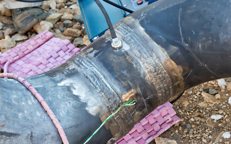

Weld root penetration is crucial for ensuring strong, defect-free joints, particularly in high-stakes industries such as oil and gas, aerospace, and heavy construction. With insufficient penetration, welds suffer from weak bonding, porosity, or failure under stress. Troubleshooting weld root penetration issues requires a systematic approach that addresses both the weld preparation and welding parameters.
Although much of this information is outlined in welding procedure specifications (WPS), this guide highlights practical tips to clarify specifics that may be unclear or omitted in your processes.
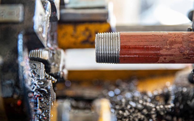
Poor Joint Fit-Up
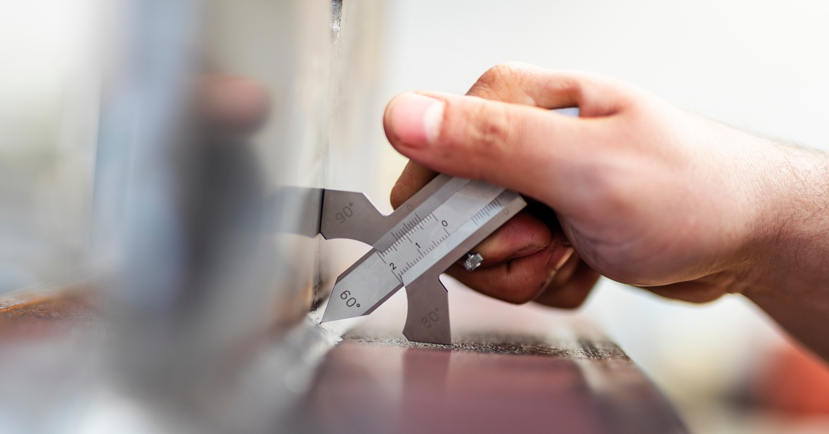
Upholding the correct joint alignment and gap is vital for optimal root penetration. Practically, misalignment refers to how well the two pieces line up, measured with straightedges or feeler gauges to check for uneven surfaces that could disrupt the weld pool.
The root gap, or the space between joint edges, should match recommended values based on material thickness and welding method, often ranging from 1/16 inch (1.5 mm) to 1/8 inch (3 mm).
Use calipers or feeler gauges to verify these dimensions before welding. Clamps, fixtures, and tack welds help maintain this alignment and gap throughout the process. During the welding, pause every 15 to 30 minutes to check for distortion or movement.
If persistent issues occur, consider redesigning joints to improve root access using a 60-degree bevel angle. Examine the edges carefully, removing any band-saw cut marks or melt-cut imperfections that could hinder fusion.
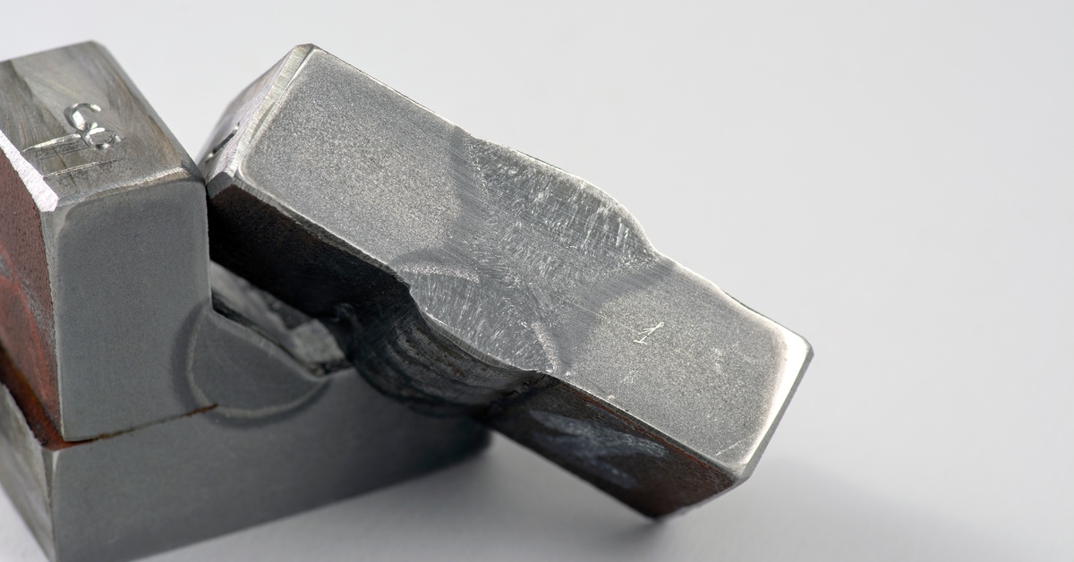
Root Face Too Thick
Controlling the root face thickness is essential for achieving proper weld penetration. While typical specifications call for around 1/16 inch (1.5 mm), slight deviations can impact fusion and strength.
Use precision measuring tools like a calibrated fillet gauge, micrometer, or thickness gauge to verify the root face before welding. Excessive thickness should be carefully ground down with an angle grinder or flap disc to meet specifications.
Should overgrinding occur, refer to the WPS to determine whether the joint remains weldable or if re-machining or part replacement is necessary.
Imprecise Heat Input
Incorrect heat input can result in insufficient penetration or an excessive weld bead size. Calculate heat input using the formula: heat input (kJ/in) = (voltage (V) × current (A) × 60) / (travel speed (in/min) × 1000).
Accurate measurement of voltage, current, and travel speed is imperative. Use welding power source meters or digital clamp meters to monitor voltage and current in real-time. Employ a stopwatch or specialized travel speed monitors designed for welding applications to monitor travel speed.
Ideal heat input varies by welding process and material. For instance, gas metal arc welding (GMAW) typically ranges from 0.5 to 1.5 kJ/mm, whereas shielded metal arc welding (SMAW) may require higher inputs, depending on the electrode size and material thickness.
Inconsistent Travel Speed
Inconsistent travel speed is a frequent cause of irregular bead appearance. Moving too quickly results in shallow penetration, undercut, or a ropey bead, while moving too slowly triggers excessive buildup, overheating, or burn-through.
To maintain a steady travel speed, focus on consistent body positioning and torch angles throughout the weld. Keep elbows braced when possible, and position your body to minimize adjustments mid-pass.
On longer joints, mark travel increments directly on the workpiece to use as visual guides. For even more control, consider using guide wheels or incorporating a mechanized welding system with a pipe welding machine to standardize motion and reduce variability.
Exercise controlled runs on scrap material. After each pass, inspect for variations in width, penetration, and profile to fine-tune the technique before applying it to production welds.
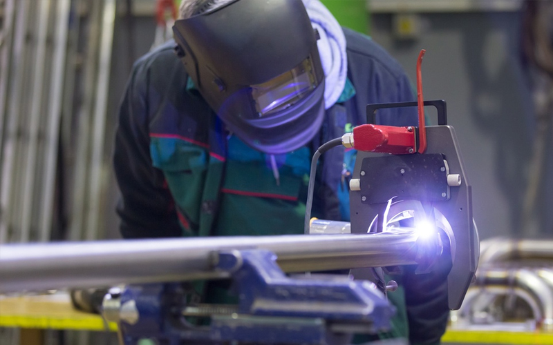
Improper Torch Angle or Positioning
Maintaining the correct torch angle and positioning is critical. Erroneous angles disrupt weld pool flow, reduce shielding gas coverage, and cause inadequate fusion or incomplete penetration. While a torch angle between 10 and 15 degrees off vertical is generally recommended, exact angles vary by process and joint configuration.
For flux-cored arc welding (FCAW), dragging the torch—holding the arc slightly ahead of the puddle—concentrates the heat at the root. A drag angle between 5 and 15 degrees is ideal. Work angles should be adjusted to 40–60 degrees, depending on the joint, with careful control over travel speed and electrode manipulation to avoid a lack of fusion.
With gas metal arc welding (GMAW/MIG), both push and pull techniques are used, but the key is to direct the arc at the leading edge of the puddle to maximize depth. Poor torch control, excessive angles, or wavering arc focus all lead to inconsistent fusion and erratic bead shape.
Practice with test coupons in different positions to refine the torch technique.
Wrong Electrode or Filler Metal
Using the wrong filler metal or electrode severely limits root penetration, especially in out-of-position welds or thicker materials. Even when base materials and joint prep are correct, mismatched filler choices can undermine arc characteristics, deposition rates, and fusion at the root.
Selecting electrodes or wires based on availability or general-purpose classifications—like “all-position”—can introduce certain complications. Some flux-cored wires designed for multi-position welding (e.g., E71T-1) tend to deliver lower penetration than wires developed specifically for flat or horizontal use.
For flat (1F) or horizontal (2F) fillet welds, switch to a flat-position-specific flux-cored wire such as E70T-1C/M to improve bead profile. If the joint design permits, step up to a larger wire diameter (e.g., 0.052 inch or 1/16 inch) to allow for higher amperage and better root fusion. Always refer to the WPS for allowable substitutions, and consult consumable data sheets for recommended settings, polarity, and deposition characteristics.
When using solid wire or stick electrodes, double-check compatibility with base metal grade and joint type, particularly when transitioning between mild steel, stainless, or dissimilar metals.
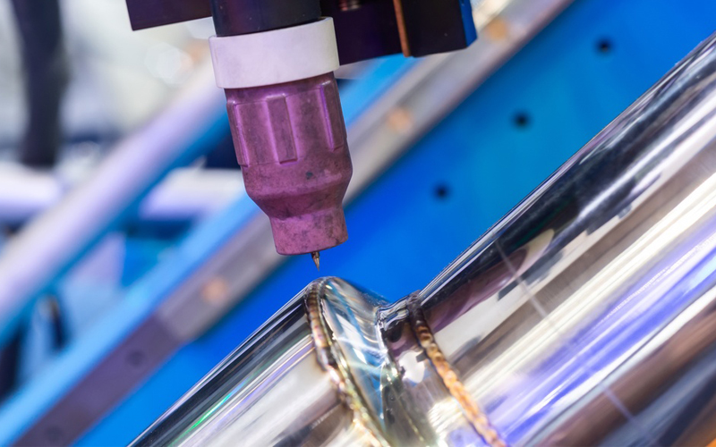
Incorrect Shielding Gas
Using the wrong shielding gas—or using the correct gas with poor flow control—directly impacts arc stability and bead quality. Each welding process and filler metal requires a specific shielding gas composition to protect the molten weld pool and promote the desired fusion.
For example, using 100 percent CO₂ with solid wire (GMAW) increases penetration but can cause spatter and porosity if not properly tuned. In contrast, a 75/25 argon-CO₂ blend offers a cleaner arc with good penetration and reduced oxidation for mild steel. Employing too much argon in a flux-cored application may result in a colder arc and a lack of fusion at the root.
Gas flow rates also matter. Too low, and atmospheric contamination can occur; too high, and turbulence may pull oxygen into the arc. Preferably, set flow rates between 20–30 CFH, use a gas diffuser, and ensure hoses and fittings are leak-free. Always match the shielding gas type and flow rate to the WPS, filler metal, and welding position.
Invest in Prevention
Even when working from a well-written WPS, it’s easy to overlook specific variables that affect weld root penetration, such as the state of the equipment. If you’re struggling with repeatability, upgrade to a system designed to control key welding parameters. A pipe welding machine with programmable settings can offer more consistent arc control, travel speed, and wire feed than manual welding setups, resolving penetration problems at their source.
Troubleshooting weld root penetration issues is more than checking boxes on a spec sheet; it’s about translating process knowledge into consistent execution. For specialized support or equipment that delivers, partner with SEC Industrial. We provide custom-engineered pipe welding, cutting, and beveling equipment built for performance and backed by a level of service unmatched in the industry.